



ADC12DL3200 Replacement: GX12D3200 Pin-to-Pin Dual 3.2 GSPS ADC
GX12D3200 is a dual-channel, 12-bit high-speed ADC developed for RF direct sampling, broadband data acquisition, radar, satellite receivers, electronic warfare and high-speed test equipment.
The device integrates two 12-bit ADC channels operating at up to 3.2 GSPS per channel. It can also operate in an interleaved single-channel mode with a maximum sampling rate of 5 GSPS.
GX12D3200 uses a parallel LVDS output interface supporting Demux-by-1 and Demux-by-2 operation, two or four LVDS data buses and signaling rates up to 1.6 Gbps per LVDS pair. Its AutoSync function supports deterministic synchronization of multiple ADCs installed on the same board or across multiple boards.
The FCBGA256 package and pin-compatible hardware architecture allow GX12D3200 to be evaluated for existing ADC12DL3200 designs. Sampling mode, power supplies, SPI configuration, LVDS timing and thermal conditions must be verified before replacement.
GX12D3200 as an ADC12DL3200 Replacement
In dual-channel mode, GX12D3200 matches the principal ADC12DL3200 operating point by providing two 12-bit channels with sampling rates up to 3.2 GSPS per channel.
GX12D3200 can therefore be evaluated as a pin-to-pin replacement for dual-channel ADC12DL3200 systems operating at or below 3.2 GSPS.
In single-channel mode, GX12D3200 supports sampling rates up to 5 GSPS, while ADC12DL3200 supports up to 6.4 GSPS. GX12D3200 is suitable for ADC12DL3200 single-channel applications whose required sampling rate does not exceed 5 GSPS, but it is not a full-speed substitute for systems operating between 5 GSPS and 6.4 GSPS.
GX12D3200 can also be selected for new high-speed digitizer and RF-sampling designs requiring dual-channel acquisition, flexible parallel LVDS output and multi-device synchronization.
Pin-to-Pin Hardware Compatibility and Migration Conditions
GX12D3200 is supplied in a 256-ball FCBGA package with a 17 mm × 17 mm body and 1 mm ball pitch, supporting pin-to-pin hardware migration from ADC12DL3200.
The parallel LVDS architecture supports the same principal interface configuration used in ADC12DL3200 systems:
l Demux-by-1 operation using two LVDS data buses
l Demux-by-2 operation using four LVDS data buses
l Up to 48 LVDS data pairs
l LVDS signaling rates up to 1.6 Gbps per pair
l Offset-binary or two’s-complement output formats
l Multi-device synchronization
GX12D3200 specifies a data latency of 30 sampling-clock cycles in the default LALIGNED = 0 mode. ADC12DL3200 specifies a digital latency of 26 device-clock cycles in its corresponding LALIGNED = 0 configuration. Existing FPGA or ASIC capture logic may therefore require latency and frame-alignment verification.
Pin-to-pin hardware compatibility does not by itself establish SPI-register or initialization-software compatibility. The existing ADC12DL3200 register settings, startup sequence, calibration control, synchronization configuration, output formatting and LVDS capture logic must be compared with the GX12D3200 programming specification.
Power-supply implementation must also be checked. ADC12DL3200 uses 1.9 V analog, 1.1 V analog and digital, and configurable LVDS interface supply rails. GX12D3200 is specified in the supplied product information as using a 1.9 V single-supply architecture. The function and voltage requirement of every FCBGA power ball must be confirmed before installation on an existing board.
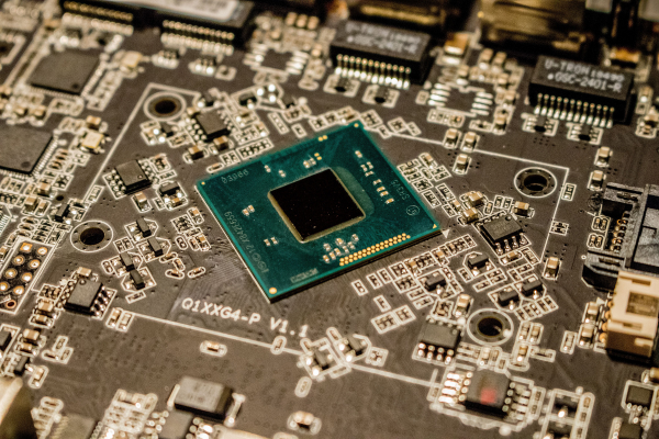
GX12D3200 vs ADC12DL3200: Key Specification Comparison
|
Specification |
ADC12DL3200 |
GX12D3200 |
|
Resolution |
12-bit |
12-bit |
|
ADC Channels |
2 |
2 |
|
Input Type |
Differential |
Differential |
|
Maximum Dual-Channel Sampling Rate |
3.2 GSPS per Channel |
3.2 GSPS per Channel |
|
Maximum Single-Channel Sampling Rate |
6.4 GSPS |
5 GSPS |
|
Data Output Interface |
Parallel DDR LVDS |
Parallel LVDS |
|
LVDS Demultiplexing |
Demux-by-1 / Demux-by-2 |
Demux-by-1 / Demux-by-2 |
|
Number of LVDS Data Buses |
Two or Four |
Two or Four |
|
Maximum LVDS Data Pairs |
48 |
48 |
|
Maximum LVDS Data Rate |
1.6 Gbps per Pair |
1.6 Gbps per Pair |
|
Output Data Format |
Offset Binary / Two’s Complement |
Offset Binary / Two’s Complement |
|
Digital Latency in LALIGNED = 0 Mode |
26 Device-Clock Cycles |
30 Sampling-Clock Cycles |
|
Multi-Device Synchronization |
SYSREF, Strobes and Automatic SYSREF Calibration |
AutoSync for Same-Board and Cross-Board Cascading |
|
Published Power Consumption |
3.15 W in Specified TI Operating Mode |
Less Than 2 W |
|
Main Supply Information |
1.9 V and 1.1 V Rails |
1.9 V Single-Supply Architecture |
|
Operating Temperature Range |
−40°C to +85°C |
−55°C to +105°C |
|
Package |
FCBGA256 |
FCBGA256 |
|
Package Body Size |
17 mm × 17 mm |
17 mm × 17 mm |
|
Package Height |
Up to 3.31 mm |
1.36 mm |
|
Ball Pitch |
1.0 mm |
1.0 mm |
|
Pin-to-Pin Hardware Compatible |
— |
Yes |
|
Existing SPI Software Directly Reusable |
— |
Requires Register-Map Verification |
|
Existing FPGA LVDS Logic Directly Reusable |
— |
Requires Latency and Timing Verification |
GX12D3200 matches the main dual-channel sampling rate and parallel LVDS interface structure of ADC12DL3200 while providing lower stated power consumption and a wider operating-temperature range.
The lower 5 GSPS single-channel limit and different stated digital latency must be considered during replacement evaluation.
Parallel LVDS Output and AutoSync Operation
GX12D3200 supports a flexible parallel LVDS interface designed for direct connection to an FPGA or ASIC.
In Demux-by-1 mode, the output uses two LVDS data buses. In Demux-by-2 mode, four LVDS data buses reduce the data rate handled by each receiving bus. Up to 48 LVDS data pairs can be used, with signaling rates up to 1.6 Gbps per pair.
Output samples can be programmed in either offset-binary or two’s-complement format, allowing the digital data format to be selected according to the receiving signal-processing system.
The integrated AutoSync function supports synchronization of multiple GX12D3200 devices. It can be used for multi-ADC cascading on one board or for synchronized acquisition across multiple boards.
Key GX12D3200 features include:
l Dual 12-bit high-speed ADC channels
l Up to 3.2 GSPS per channel in dual-channel mode
l Up to 5 GSPS in single-channel mode
l Differential analog inputs
l Parallel LVDS data output
l Demux-by-1 and Demux-by-2 interface modes
l Two or four LVDS data buses
l Up to 48 LVDS data pairs
l LVDS data rate up to 1.6 Gbps per pair
l Offset-binary and two’s-complement formats
l 30-sampling-clock-cycle latency in default LALIGNED = 0 mode
l AutoSync multi-device synchronization
l Same-board and cross-board ADC cascading
l Power consumption below 2 W
l −55°C to +105°C operating-temperature range
l FCBGA256 package with 17 mm × 17 mm body and 1 mm ball pitch
GX12D3200 is suitable for:
l RF direct downconversion and direct sampling
l High-speed data acquisition systems
l Ultra-wideband satellite data receivers
l Automatic test equipment
l High-speed test instruments and digitizers
l Wideband radar systems
l Electronic warfare systems
l Multi-channel synchronized acquisition systems
Replacement Verification and Technical Support
GXSC can provide samples, pinout comparison and technical support for ADC12DL3200 replacement projects and new RF-sampling designs.
Before approving a replacement, engineers should verify:
l Complete ADC12DL3200 ordering code and package version
l Dual-channel or single-channel operating mode
l Required maximum sampling rate
l Complete FCBGA256 ball-map correspondence
l 1.9 V, 1.1 V and LVDS interface supply connections
l Analog input range, common-mode voltage and termination
l Sampling-clock frequency, amplitude and jitter
l SYSREF and synchronization signal configuration
l SPI register map and device initialization sequence
l Foreground or background calibration requirements
l Demux-by-1 or Demux-by-2 output mode
l LALIGNED configuration
l Offset-binary or two’s-complement output format
l LVDS bus count, lane assignment and signaling rate
l FPGA or ASIC capture timing
l Difference between 26-cycle and 30-cycle digital latency
l Multi-device synchronization and deterministic latency
l Package height, heatsink contact and mechanical clearance
l Power consumption and thermal design
l Operating-temperature requirements
Request the GX12D3200 Datasheet, Samples and Migration Support
Contact GXSC to request the GX12D3200 datasheet, FCBGA256 ball-map information, SPI programming documentation, samples, quotation or technical support.
For ADC12DL3200 replacement evaluation, please provide the complete original ordering code, operating mode, sampling rate, power-supply configuration, SPI initialization settings, LVDS interface configuration, FPGA timing requirements and synchronization architecture.

 mail
mail